22
Aug
08

DIY Environment maps – Part 1

Using an environment map for lighting in Photoworks can be a simple method to light both parts and assemblies in a standard way .

I do have a problem though with the environments supplied in Photoworks, as they are all visually very busy, resulting in inappropriate highlights in a rendered model.

What I really need is a simple set-up that replicates a photo studio used for photographing component parts.  I would set up the part on a white continuous back ground with a couple of lights out front and a reflector over head, in this way I could get a clean photo of the model each time.

I can replicate this with a mini studio in Solidworks, and have done, but it can be simpler and quicker to use an environment.

The standard environments do not include a simple studio set up, so I wondered if I could create one. I did some research on the requirements and came to the conclusion that I could do it in Photoshop without taking a single photograph.

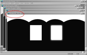
I started in Photoshop with a new document 1500 x 750 pixels at 72 DPI and 16bit colour mode. What I needed was a mainly black background with a couple of rectangular boxes to represent the light sources and a reflective area above. The image shown below was what I came up with.

I have one intense light and one less intense and a bit blurred around the edges. The pelmet at the top was my attempt to create a shape that would resolve into a square when laid into a spherical environment.           ( didn’t actually work that well but it still serves its purpose. )

As you may now imagine this is all being done pretty much by guess work so the results may not be optimal in terms of what could be achieved, but hey it did work. This then will be the basis for HDR file that can be created in Photoshop, but also more simply in a program called Photomatix basic.

To create the HDR file you need several images that represent what a camera would have taken with over a range of exposure settings. I created 3 16bit files one at nominal and then one effectively 1 stop higher and then another one stop lower. These images shown below have the RGB values for the 4 elements in the image shown below to give you a starting point for your own trials. The files were created by copying the original twice and then adjusting the RGB value for each of the elements in turn.

RGB Values

Pelmet 237,237,237
Window L 255,255,255
Window R 237,237,237
Background 71,71,71

RGB Values

Pelmet 172,172,172
Window L 244,244,244
Window R 216,216,216
Background 29,29,29

RGB Values

Pelmet 75,75,75
Window L 230,230,230
Window R 179,179,179
Background 18,18,18

When the images are complete you can either take them into ‘Merge to HDR’ in Photoshop or open Photomatics basic and process them there. I tried to do it in Photoshop but couldn’t get on with it so I used Photomatix (www.hdrsoft.com), and that is what I shall use for the rest of this exercise.

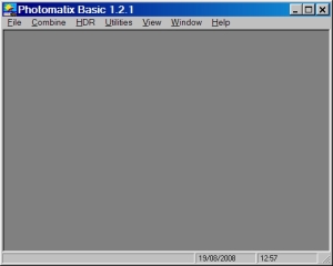
This is the opening screen for Photomatix.

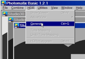
Go to file and open the 3 files that have been

generated in Photoshop, and then click on

‘Generate’ under the HDR menu item.

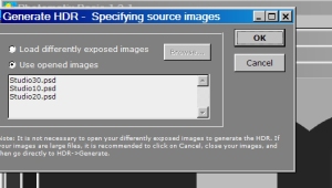
Make sure the radio button is on ‘opened images’ and click OK.

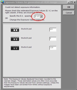
The 3 images should then be brought up in order as they are above, you need to adjust this value,

I used 2.5 as that seemed to work.

hdr-10

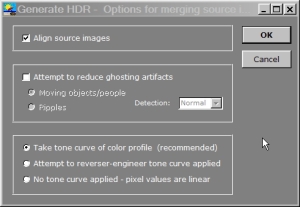
Click through with the defaults on this next screen

This screen shows the generated image and allows you with a magnifying box to examine the image.

Finally save the file to your hard disk where you can find it again. It might be wise to save it here
C:\Program Files\SolidWorks \SolidWorks\data\Images\textures\background\
where all the other HDR files are kept.

If you would like to try the the file created here you can email me and I will send you a copy.

In part 2 of this feature I will go through the steps needed to use the file you have created.

31
Aug
07

impressed me

This is to be a weekly round up of sites I have found that I think are worth a visit. They are not all related to topic, but I enjoyed them any way.

This first one is Photoshop related and illustrates an excellent and easy to use technique for improving your photo’s.

2007-08-31_174323.jpg

I needed a blood pressure chart the other day and a search of the internet found this, its really comprehensive and helps to explain your BP very clearly.

2007-08-31_174800.jpg

I wish I could do this, just so impressive.

2007-08-31_175221.jpg

I love to see animations of mechanisms and engines, this site has them all done in 2D.

2007-08-31_175611.jpg

28
Aug
07

making an impression with solidworks Part 3

Before we can start with the rendering in Photoworks we need to set up a new folder into which we can store the materials that will be used in this project. This of course is not always necessary as you can set up a standard folder with the materials and finishes that you will generally use. In this case I have created a folder at C:/Colours/Photoworks Colours/Toothpaste. I like to keep these specials separate from the normal Solidworks directory structure just in case the settings get lost at some point. (As you can guess this has happened in the past.)

file-location-1.jpg

When this directory is in place we can have Solidworks access it by clicking on the Material in the Photoworks Items column on the Right side of the screen, and then clicking on the ‘Add file location symbol’

file-location.jpg

Now we can start adding materials to the model and saving them to the toothpaste directory, but before we can do that we need to identify the colours that we are going to use. I have decided to use a scanned image of a label from a toothpaste dispenser for this project, so the colours are going to be taken from that. I have used ColorCop for this purpose as it will store the colours in a column on the right side of the ColorCop window and display the RGB values. You can configure this small application to stay on the top of the screen so you can have it visible whilst you enter the RGB values into PhotoWorks. The picture below shows the ColorCop window open beside the model and the Actuator part highlighted.

colour2.jpg

Having identified the part we wish to apply the material to we now need to open the materials menu which is shown below.

colour1.jpg

This opens the menu and allows us to enter the RGB values for the colour to be used on the actuator. There are a lot of setting that can be made here but we are only concerned at the moment with colour the illumination and then saving this to the toothpaste directory we set up earlier. I managed to clip off most of the bottom box where the RGB values are typed in, but you can just see the value for red at the very bottom. Add the other two values as well for green and blue and the click on the illumination tab at the top of the menu.

colour3.jpg

The Illumination dialogue collects the information that determines how the surface will react to the light shone on it, so if it is highly reflective plastic or metal surface, clear glass or textured, all of the settings are contained here. The setting shown below will give a reasonable impression of a gloss plastic without being over the top. We are not trying to create Photo realism with this render, so we don’t need highly reflective surfaces that white-out when rendered, but we do need to see and understand the construction of the model we are rendering.

colour4.jpg

Now that the material has been defined we need to save the material we have created to the toothpaste directory. To do this go back to the original Color/Image tab and click on save ,find your directory and save the material.

colour5.jpg

Once you have colours defined and appearing in the Photoworks Items menu on the right side of the screen, you can use that menu to drag the colour onto the part, but you do need to define the colours first. I have shown below how you can drag the yellow coloured material onto the flexing piston.

colour6.jpg

In the next instalment we will get to apply the label (Decal) to the tube and then render the images.

27
Jul
07

Searching for Patent information

I had to find some patents the other day so that I could quickly check that a new design I was working on was not likely to infringe any prior art. This can be a terribly time consuming process but it did strike me that it’s a lot easier than it used to be, before access to patent on the internet became really effective.

There are two really good sources of patent data on the internet, and I am sure there are more but these are the ones I am familiar with and use most often. the first is Freepatentsonline and the other is Google Patents They are both effective at at find patents through either a simple or advanced search field and both will allow you to download PDF files of the patents for printing.

One of the features I find useful with both, is that they effectively allow you to find patents on a very restricted subject range by including data on patents are cited by, and patents that cite, the one you are viewing, so you can get a full spectrum of patents from the first on the subject through to the most current.

The trick is to find a single patent that most clearly meets the criteria for which you are searching, and that of course is the hard bit, as you must clearly define your search term so as to avoid sorting through all the chaff.

The following images show pages from both sites, whilst searching for patents on toothpaste dispensers.

google-patents.jpg google-patents2.jpg google-patents3.jpg patentsfree-c.jpg patentsfree-a.jpg patentsfree-2.jpg patentsfree-b.jpg

21
Jul
07

Making an impression with Solidworks – Part 2

I am going to work through this demonstration using a model of a toothpaste dispenser, which can be seen in the image below.

I shall do the demonstration in 3 steps, this first step will be the setting up of the model in Solidworks to make the necessary section cuts, and the creation of a separate configuration to show the actuator in a pressed down position.

The model is going to be sectioned twice so that we can build up a layered view that gradually peers deeper into the inner workings of the model.

tp-1a.jpg

This view shows the model loaded into Solidworks and ready for the first section cut to be made.

tp-2.jpg

The cut shown above will be a straight rectangular cut with the top left corner on the centre line .

tp-3.jpg

Having sketched the cut then find the Extrude cut tool in the pull down menu as shown above , click on this to reveal the preview shown below.

tp-4.jpg

Grab the ends of the arrows to extend the yellow preview cut box both up and down to the full extent of the cut required. Now click on the Auto select arrow to deselect it, and then on the assembly component symbol indicated above to open the parts tree .

tp-5.jpg

tp-6.jpg

Clicking OK makes the cuts only through the parts that were designated to give you the finish shown above.

NB! The actual parts themselves have not been cu, only their representations in the assembly.

tp-7.jpg

The second cut uses the same sketch as the first, we have only split the cutting operation so that separate states can be used later for rendering.

tp-8.jpg

That’s all the cuts we need to do and these can be now used sequentially for rendering at the next stage.

Before we move onto that we need to create another configuration to show the actuator, the red lever at the top, pressed down fully showing deflecting the flexing piston.

To be able to do this there needs to be a second configuration for the Flexing diaphragm as well, the too configurations for that are shown below

tp-13.jpg tp-14.jpg

Using the above Flexing piston configuarations we can then create the two configurations for the Actuator, and these are shown below.

tp-11.jpg

tp-12.jpg

We have now completed all of the basic work in Solidworks to create are multi-layered renders at the next stage.

16
Jul
07

Capturing colours

There are a couple of small applications that make it a lot easier to capture the colours you want to use in your render.

The first is Faststone Capture this lets you grab a section of the screen and save it to disk. This can be used to capture colour pallets that you can then use in conjunction with ColorCop. This has an eye dropper tool that can capture around 8 separate colours from any whereon the screen.

Using these tools in combination you can capture a pallet or any other area of colour with FastStone and then use ColorCop to capture the individual RGB values.

ColorCop will stay on top of other running applications so that it is visible whilst using Photoworks so you can copy the RGB values into the Photoworks pallet. This is a great time saver and very accurate, just a pity Photoworks doesn’t have its own Eye dropper tool, but then that would be too easy.

ColorCopCorner

ColorCop shown here sitting on top of the Photoworks screen adjacent to the colour pallet with the RGB values shown.

15
Jul
07

Choosing Colours

I am an Engineer so I have a problem when it comes to working with colours

For years choosing the right colours to use in presentations was very difficult, and I always had to rely on the designers I worked with to put me right.

Now I work for myself things could have been a lot a harder, but I found the solution on the internet.

There are any number of sites out there willing to tell you the right colour combinations to use, but there are two that I find are really useful.

They both use 5 colour pallets which is great when you have a large number of components in a cross section to differentiate.

They both also rate the pallets, so you judge if a colour scheme works for you, and also have the confidence to know that a lot of other people agree.
goodfriends.jpg   www.coulourlovers.com

firenze.jpg  kuler.adobe.com


If you sign up to the sites you can download the colour pallet of your choice directly as a Photoshop colour swatch and then use the eyedropper tool to identify the colour as an RGB value for inclusion into Solidworks or Photoworks.

There is a more convenient way of working with these colour pallets within Solidworks and Photoworks which I will discuss in the next posting.

13
Jul
07

Making an Impression with Solidworks

Ever wanted to make more of the Solidworks models you have created, then of course you can, as you have already done most of the hard work.

The purpose of this site is to show you how you can create presentations with real impact and style, by using the your basic model data plus a couple of other pieces of creative software.

To make any start at all you will need to have Photoshop installed and for preference Photoworks the standard rendering plug-in for solid works.

These two software applications will cover most of your needs although there are several useful applications that will be discussed at a later date.

To show you the type of output that is possible I have included the image comparison shown below. On the left is an original screen dump of the model showing the cutaway section and on the right is the same model generated with Photoworks and Photoshop.

toothpastecompare.jpg

This final image is ready for inclusion into a presentation. It shows a partial cross section through the model blending out towards the bottom. It has been rendered in Photoworks and has a decal (Label) fitted to the outside of the container. The model was selectively sectioned in Solidworks leaving the red lever complete, so as to give the finished image more depth. Two renders were made, the first of the cross section and the second as an un-sectioned model and then the two combined in Photoshop.

For the moment this is the end of this first post on Solid Impression, and I hope over the next few weeks to show in detail how this image was created, and then go onto ever more interesting things related to Solidwork, Photoworks and Photoshop.